
Detector & Physics in Zeuthen for a Linear Collider
An optical cavity for power enhancement
Creation of high energy photons:
Compton backscattering of low energy (around 1 eV) laser photons is the most promising process for efficient creation of high energy γ photons in the range of several hundred GeV. The upconverted photons tend to propagate in the flight path of the electrons. According to a calculation of this process with the CAIN Monte Carlo program a luminosity of electron-photon and photon-photon collisions comparable to that of the e+e¯ collision mode in the same collider can be obtained with suitable laser and electron beam parameters. A prerequisite is a short distance (2.1 mm for TESLA) between the Compton conversion point (CP) and the γγ interaction point (IP). Thereby a substantial degradation of the achievable photon density owing to the additional angular spread of order of 1 µrad from the Compton backscattering process can be prevented. This necessitates to place the focussing optics for the laser beam within the limited space of the particle-detector enclosing the interaction region without interfering with the performance of the detector and obstructing the optical beam.
Moreover, the polarization of the gamma quants can be varied and controlled by that of the laser beam. This flexibility contributes to the discovery potential of a TeV linear collider.
Laser requirements:
In order not to loose the produced photons by the reaction γγ → e+ e¯ one needs for an electron beam of 250 GeV energy a laser wavelength around 1 µm. This coincides with the emission wavelength of the most powerful solid state lasers. For achieving a high γγ-luminosity the low energy photons are focussed onto the particle beam and must come in bunches of a duration that matches the electron bunch length of 0.3 mm and collide head-on with the beam from the accelerator. However, for avoiding excavated optics with a central hole a crossing angle α0 ≠ 0 has to be introduced. Its value is determined by the accepted extent of diffractive broadening of the laser focus that occurs due to the influence of limiting mirror apertures, the size of the final focussing mirror beeing the most crucial factor. In the course of an iterative optimization of the γγ-luminosity we found an aperture a for the final focussing mirror given by a/w =0.75 is still acceptable. w represents here the Gaussian beam radius that would exist at this position if all mirrors were unbounded.
The optimization of the γγ-luminosity for 2E0 = 500 GeV resulted in:
- Rayleigh length ZR at CP 0.63 mm
(TESLA-TDR, part VI, page 42: ZR = 0.35 mm)
This corresponds to 7.7 µm r.m.s. (14.9 µm (1/e²) ) focal spot size. - collision angle α0 = 55.1 mrad
- laser pulse energy: 9.0 J
- laser pulse duration: 1.5 ps (r.m.s.) or resp. 3.5 ps (FWHM)
- total luminosity L γγ(z > 0.8zm,γγ) = 1.05 * 1034 cm-2 s-1, (TESLA-TDR, part VI, table 1.4.1: L γγ(z > 0.8zm,γγ) = 1.1 * 1034 cm-2 s-1)
- nonlinearity parameter ζ2 = 0.30 (TESLA-TDR, part VI, section 1.4.5.2: ζ2 = 0.30)
- 2820 bunches/train,
- 337 ns spacing,
- 5 Hz repetition rate,
they require a laser with a jitter of less than 1 ps and capable of delivering of ≈ 2 TW peak power as well as high average power (≈ 100 kW). At this power level far more than 50% of the electrons in a bunch will Compton backscatter. A laser source with such parameters currently is out of reach applying state-of-the-art laser technology. On the other hand only a very small fraction (≈ 10-7 ) of the laser photons is spent on this process. So it appears to be much more economical to reuse the laser pulse several times. For this reason we suggest to use an external storage ring which ensures multipassage of the laser beam. Such a cavity could be established in a purely passive resonant as well as in a regenerative mode. For the required high power level intensity-dependent contributions to the index of refraction are non-negligible. They can easily result in beam distortion or even filamentation if the effective optical path length is sufficiently large. To reduce these potential risks a passive cavity avoiding transmissive optics is preferred. For the actual γγ-collider two identical versions of such a cavity have to be nested around the detector. In the following only one cavity is considered.
Optical cavity:
The concept of a passive optical cavity permits resonant enhancement of the circulating optical power by stacking the energy from a laser with reduced power capability that feeds the resonant ring cavity with the correct pulse structure. For the TESLA format this requires a circumference of ≈ 101 m. A sketch of the proposed resonator is shown on top of this page. A telescopic convex-concave mirror arrangement focusses the beam down to the diffraction limit set by the size of the final concave mirror and an identical combination recollimates it again. The plane mirrors fold the optical path around the detector. They also provide the location for the potential option of adaptive mirrors to correct slight deformations of the optical wavefront (preferable at the position of the mirrors adjacent to the telescope). Another option could be a discoidal amplifying mirror next to the coupling mirror for the laser. The complete optical beam pipe has to be kept at machine vacuum level.
A power enhancement factor A of the order of 100 seams to be feasible with reasonable R&D effort. Hence, the required laser power might be reduced by the same amount. This task requires an advanced electronic feedback system for control of cavity length and mirror tilts.
|
|
||||||||||
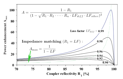
Because of energy loss due to diffraction, scattering, absorption etc. the cavity has a total loss factor LF < 1. The enhancement can be maximized by an exact matching of the reflectivity of the coupling mirror and the total lossfactor Ldiff · Lother. According to a physical optics calculation for a geometry adapted to the TESLA-detector a diffraction lossfactor LFdiff ≈ 1-10-4 is to be expected. Assuming high quality mirrors with reflectivities R ≥ 99.9% the envisaged enhancement is feasible when the transverse modeprofile of the laser is also matched to the mode building up within the cavity.
Build-up of power
|
|
|
Numerical example of loading an empty cavity: left: development of power enhancement factor for increasing number of roundrips of the optical pulse; right: development of transverse optical mode profile at the inner side of the coupling mirror, vertical axis: intracvity power (arb.un.), x-axis: cross-sectional coordinate (cm), y-axis corresponds to roundtrip-number. |
|
The numerical results for a Gaussian seed, Rcoup ≥ 99% and a/w =0.75 demonstrate that for this example roughly 1000 extra laser pulses are needed for completion of the power build-up inside the cavity.